Stand alone "room in a room" studio build in Orange NSW Australia

Document your build here: All about your walls, ceilings, doors, windows, HVAC, and (gasp!) floated floors...
gearjunk1e
Full Member
Posts: 104
Joined: Sun, 2021-Mar-07, 19:19
Location: Orange Australia

Stand alone "room in a room" studio build in Orange NSW Australia

#46

Postby gearjunk1e » Sun, 2024-Mar-10, 19:20

Thanks both of you

My filters are located in easy access in the workshop area adjacent and I'm confident in my joins (caulk, tape, double hose rings) so I'll drop the trapdoors :yahoo:

I've not posted for a while on progress - just working through ceiling modules
20240311_085338.jpg
CR ceiling half done
20240311_085338.jpg (31.04 KiB) Viewed 4116 times
20240311_085338.jpg
CR ceiling half done
20240311_085338.jpg (31.04 KiB) Viewed 4116 times
and I had to spend a bit of time on the Live Room as the mate I borrowed the nailer from needed it back for big job - a very good friend - I had it here for 2.5 years! I'd left behind two last substantive framing jobs - the infill framing between the joists
20240311_085407.jpg
in fill framing 1
20240311_085357.jpg
in fill framing 2
and the corner framing around the shed frame double post
20240311_085426.jpg
double column
- so I spent some time on those jobs while I had the nailer. Back on the CR ceiling this week :D

Any thoughts on the question on the wings :?:


User avatar
gullfo
Senior Member
Posts: 620
Joined: Fri, 2021-Jun-25, 14:50
Location: Panama City Beach, FL USA

Stand alone "room in a room" studio build in Orange NSW Australia

#47

Postby gullfo » Sun, 2024-Mar-10, 20:53

generally you want the soffits below the edge of the console or desk to be absorptive - so routing wiring in the lower section should not be an issue. many times you can create a wiring trough across the front to keep things need and cover it.


gearjunk1e
Full Member
Posts: 104
Joined: Sun, 2021-Mar-07, 19:19
Location: Orange Australia

Stand alone "room in a room" studio build in Orange NSW Australia

#48

Postby gearjunk1e » Tue, 2024-Mar-12, 18:37

Thanks Glenn
Having posted on this subject I then came across the last few pages of Gareth's blog (the rectification) which is super helpful on this question - and more than a few others regarding control room design :oops: Not sure how I missed it as I'd watched this build quite closely
Andrew


gearjunk1e
Full Member
Posts: 104
Joined: Sun, 2021-Mar-07, 19:19
Location: Orange Australia

Stand alone "room in a room" studio build in Orange NSW Australia

#49

Postby gearjunk1e » Sat, 2024-Jun-01, 07:10

I'm way overdue for an update but the short story is that I've finished the control room isolation work - I have a room with only one door and no internal treatment other than bales of insulation in the corners as crude bass traps. It is set up as a multi purpose room at the moment.
More to come ASAP on the detail...including pics and "raw" room measurement files using Stuart's walking mic method

In the meantime, 2 questions:

1. What is the difference between using neoprene and natural rubber for the job of decoupling? (the specific application is the rubber between the bearers and the inner silencer base)

2. My electrician used flexible conduit for the ethernet and electrical runs. He did the penetrations so they were "non aligned" but I forgot to remind him to leave a gap in the conduit between the walls so that I could join them with rubber to reduce flanking risk. The conduit is pictured here
20240601_204302.jpg
- it is only 0.5mm thick and I have been filling around the penetrations with "Big Stretch" per the second pic.
20240601_204323.jpg
So the QUESTION is "how much risk am I taking by not getting him to create a gap for me to join with rubber?"

Andrew


User avatar
gullfo
Senior Member
Posts: 620
Joined: Fri, 2021-Jun-25, 14:50
Location: Panama City Beach, FL USA

Stand alone "room in a room" studio build in Orange NSW Australia

#50

Postby gullfo » Sat, 2024-Jun-01, 10:51

i've used that type of flex conduit in several jobs, and as long as the conduit isn't stretched tight, i find that it works ok. if you needed a larger conduit for multiple plenum type cables between rooms - then the rigid conduit + rubber decoupled would be the choice. keeping all electrical wiring "loose" (meaning leave some loops what crossing separated structural assemblies) so you're not short circuiting the isolation elements.

on the natural vs neoprene rubber - you'd need to check the durometer of the material vs the intended loading. i think neoprene (when you cannot use sorbathane, sylomer, or other product intended for isolation) has a better range of durometer choices and thicknesses in order to get the right material and price for the task.


gearjunk1e
Full Member
Posts: 104
Joined: Sun, 2021-Mar-07, 19:19
Location: Orange Australia

Stand alone "room in a room" studio build in Orange NSW Australia

#51

Postby gearjunk1e » Mon, 2024-Jun-03, 07:17

Glenn
Thanks
Good advice
Andrew


gearjunk1e
Full Member
Posts: 104
Joined: Sun, 2021-Mar-07, 19:19
Location: Orange Australia

Stand alone "room in a room" studio build in Orange NSW Australia

#52

Postby gearjunk1e » Mon, 2024-Aug-12, 20:06

So – a long delayed update on my build. I have been “distracted”, helping my son sort out some financials with his business and took a 6 week vacation in the UK – longest break I’ve had from the build for 2 years.

There is a lot here so I will do this in instalments..

As indicated in post #49 – I have a “control room” that is “mostly” complete for isolation purposes. I say “mostly” complete, because:

1. I have only the inner door up and a temporary fill for the window space between the LR and CR; and
2. “Control Room” is in parenthesis as it is not being used as a control room but as a general purpose music room – for now. Getting some activity going in the space is however quite motivational. Here are some pics of the room.
20240510_153323 CR empty fr base testing.jpg
20240510_153323 CR empty fr base testing.jpg (43.69 KiB) Viewed 936 times
20240510_153323 CR empty fr base testing.jpg
20240510_153323 CR empty fr base testing.jpg (43.69 KiB) Viewed 936 times
20240510_153342 rear empty CR.jpg
20240510_153342 rear empty CR.jpg (27.24 KiB) Viewed 936 times
20240510_153342 rear empty CR.jpg
20240510_153342 rear empty CR.jpg (27.24 KiB) Viewed 936 times
20240510_215521 CR bass traps1.jpg
Crude and ugly approach but quite effective
20240510_215542 CR bass traps 2.jpg
At the outset I'd have to say that I doubt I’m breaking any new ground here but trust that others might be able to learn from my mistakes and decision processes. Of course if there are any comments or thoughts on my approach they would be greatly appreciated as I have still to build out my Live Room!

Acoustic measurements

Before I loaded in the "bass traps", a basic mixing rig and some guitar gear I did baseline measurements per Stuart’s “walking mic” testing procedure – I can confirm its boring and tedious but know it will be a really good investment. I will post on these results separately though.

I have also done a number of isolation measurements at 1m from the outside of the door when closed. 85dB is barely noticeable at 1m. While the precise measurements at this point are academic, given the absence of the 2nd door, I am getting a 31dB drop off at 1m with the single door.

Working with the CR to test some of the build elements has been quite informative – the door in particular. While the CR isolation is important, I have more tolerances than with it than the LR (given the volumes) and what I’ve learned to date will be applied to the LR to give a better outcome.

Construction of CR

CR ceiling

I have addressed this earlier when exploring the various options for hanging the ceiling material. Given the size of my ceiling modules, I found the best way to hang these was to attach cleats to the inside the top of the joists (like Stuart’s “How to Build an Inside-out Ceiling for Your Studio”), raise the drywall tight up into that frame using the lift and some blocks; put some holding screws in, caulk around the gap, then repeat the whole process for sheet 2. To finish off, I nailed more substantial cleats into the joists after pushing them tight up against the bottom of the sheets. (Pics can be found in post #40). In the end, it is pretty much per Stuart’s post on inside out ceilings, but doing the whole process in situ. For all but the last one, I found it easy to slide the insulation into the 200mm gap. On the last one it was a matter of having the insulation straddling the joists and/or using fishing line.

Some pics here including the space under the silencers – where the fishing line got a good work out.
20240312_144324 isolation of celing wall.jpg
This is how I hung the ceiling at the ends - to avoid Contact between the ceiling and wall materials. Ran a strip of rubber under these mounts to back the sealant
20240312_144324 isolation of celing wall.jpg (35.06 KiB) Viewed 936 times
20240312_144324 isolation of celing wall.jpg
This is how I hung the ceiling at the ends - to avoid Contact between the ceiling and wall materials. Ran a strip of rubber under these mounts to back the sealant
20240312_144324 isolation of celing wall.jpg (35.06 KiB) Viewed 936 times
20240313_154001.jpg
20240313_154014 CR out ins under box.jpg
20240406_090003CR outlet join pre insul.jpg
20240415_161806 last CR C sheet space.jpg
20240415_161816 last sheet CR c.jpg
20240312_130256 CR ins bk rubber.jpg
Had to use rubber as the 2nd layer around the outlet at the back as it was too tight for timber
20240312_130235 CR back ins register.jpg
20240312_195127CR Bk frame 4 ceil.jpg
used some expansion joint foam between the bearer and the wall and screwed the bearer into the joists above to decouple wall and ceiling
20240312_195140CR back ready for insul.jpg
ready for insulation - once the rubber strips are straightened!
20240406_090115CR fr sil ready.jpg
ready for insulation - you can see the outlet duct where it runs out through the wall
20240409_153227CR Fr sil frame 4 ceiling.jpg
Used some small eye bolts to keep the fishing line taut
20240410_101641CR front insul in.jpg
CR column framing

Nothing here of note other than I decided to use mdf for the 2nd layer: easier to finish (for me) and more robust. Again, really testing for the 3 columns I have to frame in the LR.
20240412_181856 col box CR.jpg
More to come on door and ventilation...


gearjunk1e
Full Member
Posts: 104
Joined: Sun, 2021-Mar-07, 19:19
Location: Orange Australia

Stand alone "room in a room" studio build in Orange NSW Australia

#53

Postby gearjunk1e » Mon, 2024-Aug-12, 20:15

I mentioned the CR is being used as a general purpose room...here's what I mean...together with a shot of the fill between CR and LR - mostly covered by the artwork for now
20240813_095736.jpg
20240813_095706.jpg
Window fill
The window space looks small but is actually 2m x 800mm - as big as I could make it without fouling the (future) rear room treatment or soffit wings at the front/side


gearjunk1e
Full Member
Posts: 104
Joined: Sun, 2021-Mar-07, 19:19
Location: Orange Australia

Stand alone "room in a room" studio build in Orange NSW Australia

#54

Postby gearjunk1e » Tue, 2024-Aug-13, 03:33

Ok - part 2
Door construction

I now know more about door hanging and frames/jambs than I ever thought I would. Despite my best efforts, the jamb was slightly warped in the frame. While this was minimal, it still made for a lot of fluffing around on the seals and stops to get good, tight seals all round. (Slim offcuts from earlier trimming of the jamb, my router and plane became my “besties” throughout the process).

(If I did it again, I’d build the jambs first, put them in place then frame around them to keep them 100% plumb and square in both dimensions OR more likely, buy the jambs without stops already cut.)

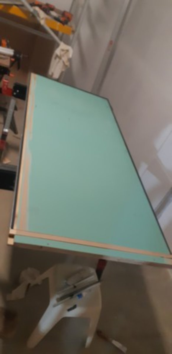
Here’s the final design of the inner door. I have e shaped rubber seals on both the door and the stop for the first stop – like a fridge door (thanks Glenn!). I added the extra pine framing on the inside of the door, around the perimeter to hold a second seal. For this, I needed an additional stop that I was able to plane and fix in such a manner so as to compensate for any irregularities – giving me a good seal between one set of rubber seals and the wood stop without adding a second rubber - like the first seal. The mdf I added on the door face only needed to be 6mm according to my target isolation calculations, rather than the 19mm I used around the perimeter to hold the additional seals – no need to over invest in unneeded weight.

The diagram only shows the seals/stops on one side of the door.
Schematic of door.png
Some pics of door construction
20240502_195502 the frame.jpg
The jamb
20240416_100404extra door width CR inside.jpg
I had to add 40mm to the latch side of the door
20240501_170108 space for door seal cut out.jpg
cut out for drop seal
20240501_170040 routing space for angle iron rubber.jpg
routing for the angle iron/rubber seals
20240502_195421temp seals rough in.jpg
Seals in for testing - yet to add the drop seal
20240502_195421temp seals rough in.jpg (40.34 KiB) Viewed 931 times
20240502_195421temp seals rough in.jpg
Seals in for testing - yet to add the drop seal
20240502_195421temp seals rough in.jpg (40.34 KiB) Viewed 931 times
20240502_212346 hanging door.jpg
Door hung with just the one set of seals
20240516_144034 finishing frame 4 2nd seal.jpg
This part was fiddly - the slight warping of the jamb meant I had to increase the width of the bottom rail (that holds the 2nd seal) as it runs across the door
20240729_181908 door from outside.jpg
20240729_181937 latch side - seal and wooden stop.jpg
The jamb side seals first to a rubber seal then the second is straight to the stop - see schematic
20240729_181954 double seal - latch side.jpg
On the door side there are 2 seals - see schematic

Ventilation

The ventilation system looks like it has been designed by the House of Frankenstein :lol: . I had ordered all my ducting, spigots, vents and knees at 5” as well as my fan and filter boxes. Then the filter box supplier came back and said that stopped making 5” units- so that became 6” and then some further engagement with the fan supplier determined the optimal model would be a 6”. So we have some reducers/expanders en route. Highlights the importance of finishing all design before you launch into materials purchasing. :oops:

It was a slow process as the mastic I used is a slow cure product, especially when you apply it thickly….but there are plenty of other tasks to do while waiting.

Anyway, here it is in all its glory….
20240326_151724.jpg
20240326_151704 inlet CR.jpg
20240326_151736 in and out.jpg
The ventilation system outflow is currently terminating in the workshop area - you can see this in the last pic. I will either decide that this is OK or finish the ventilation outlet run to the outside world at a later stage. The workshop area is FAR from sealed to the outside world so it is unlikely to present too much risk.

The C02 measurement was interesting. I will install wired C02 meters when I get the rest of the electrical work done, but for now have a battery powered one in the room. When I had my band in the room for a rehearsal just after the room was “complete”, I ran the ventilation system (der) and had the AC on circulating the air in the room. The band is a 4 piece – drummer, bass player, electric and acoustic/vocalist. The meter climbed from 430ppm to 1,000ppm after about 90 minutes. While the room ventilation has been set for 4 people in passive roles (mixing/listening), that sort of increase in CO2 is way faster than I had expected, even allowing for higher than normal activity levels for this room. More investigation to be done I think. Depending on those investigations, maybe a fan on the exhaust side may be the go.

For now, I’m back in the LR – building ventilation boxes/plenums and running ducting, audio and data cables before I finish off insulation in the walls and get back to gyprocking...but I'll post separately on the revised plan for ventilation boxes/plenums.


User avatar
gullfo
Senior Member
Posts: 620
Joined: Fri, 2021-Jun-25, 14:50
Location: Panama City Beach, FL USA

Stand alone "room in a room" studio build in Orange NSW Australia

#55

Postby gullfo » Tue, 2024-Aug-13, 11:02

nice work on the door!

yes, the 6x or more room change per hour is a guideline. and to fully perform this, you need the exhaust / return to be explicit, so another fan would be in order. one reason i usually spec an ERV/HRV - reliability, filters, energy preservation, and dual fans :-) in a single easy-to-maintain unit.

and yes, always check on available duct sizes. 6" would be "typical" although many ERV/HRV have 5" inlets/outlets... expansion on supply and contraction on exhaust are good in terms of reducing air velocity (in part determine by the 6x guide in total # of cubic units of measure per hour, and the fan air velocity needed to move it, and the exapansion options for final air velocity reduction while maintaing the volume of air needed).


gearjunk1e
Full Member
Posts: 104
Joined: Sun, 2021-Mar-07, 19:19
Location: Orange Australia

Stand alone "room in a room" studio build in Orange NSW Australia

#56

Postby gearjunk1e » Tue, 2024-Aug-13, 19:00

Glenn
Yeah - the idea of a 2nd fan came from a post(s) of yours. I looked at ERV's early on but they are not that common down here and the climate didn't scream for the heat exchange element. Quite a tidy solution. Anyway, a second fan will do the trick I'm sure and should enable me to run them on the low setting by sharing the static pressure load.
Andrew


gearjunk1e
Full Member
Posts: 104
Joined: Sun, 2021-Mar-07, 19:19
Location: Orange Australia

Stand alone "room in a room" studio build in Orange NSW Australia

#57

Postby gearjunk1e » Wed, 2024-Aug-14, 08:41

I mentioned in my last post that I’d changed the approach for silencer design for the LR. There are a few reasons:

1. Raising them into place is more complex when the registers protrude from underneath – especially at the inlet end where I have to work around the AC
2. I want to reduce exit velocity to a greater degree in the LR, so plenums are ideal
3. Getting the weight of the silencers down would make it easier to raise them into place :)

Here’s the design I used in the CR
Old.png
Extracted from Stuarts post on HVAC in the reference section
What I have in mind for the LR looks as follows
New context.png
New butt ends sealant.png
20240814_220404.jpg
Here a shot of the butt end of the silencers - the plenum will look the same at the join
New speeds.png
Register new.png
Some notes
a. The plenum still sits within the gap between the inner and outer walls so the plenum "walls" will be constructed to the same the same kg/m2 as the silencer and walls
b. I’ve shown the velocities based on the high speed of the fan which is 50% higher than my calculated fresh air requirements
c. I’m not too worried about turbulence with the 90 degree turn into the register given the speed is down to less than 100 fpm - perhaps this is naive?
d. (I'm only showing one side of course)

So here's my question :?:
Do I actually need the baffle marked in the red circle below? - the exit from the silencer and entry to the plenum has the same CSA as within the inner silencer. I put the baffle in there originally to help reduce any turbulence noise coming out of the silencer then started to think - am I better off to just get the velocity down ASAP?
question.png
Andrew


User avatar
gullfo
Senior Member
Posts: 620
Joined: Fri, 2021-Jun-25, 14:50
Location: Panama City Beach, FL USA

Stand alone "room in a room" studio build in Orange NSW Australia

#58

Postby gullfo » Wed, 2024-Aug-14, 10:42

nope.


User avatar
gullfo
Senior Member
Posts: 620
Joined: Fri, 2021-Jun-25, 14:50
Location: Panama City Beach, FL USA

Stand alone "room in a room" studio build in Orange NSW Australia

#59

Postby gullfo » Wed, 2024-Aug-14, 10:44

:D removing the baffle will allow for more even expansion. i'd probably even remove the ones on either side of the duct opening as the others will provide sufficient baffling.


gearjunk1e
Full Member
Posts: 104
Joined: Sun, 2021-Mar-07, 19:19
Location: Orange Australia

Stand alone "room in a room" studio build in Orange NSW Australia

#60

Postby gearjunk1e » Thu, 2024-Aug-15, 08:34

gullfo wrote:: i'd probably even remove the ones on either side of the duct opening as the others will provide sufficient baffling.

Ha - if only it wasn't done already I could have saved some work :oops: Anyway - good advice - thanks. I will now proceed to construction of the plenums, sans baffle :D


  • Similar Topics
    Statistics
    Last post

Who is online

Users browsing this forum: No registered users and 6 guests